
Mold Hydraulic Locking Cylinder Manufacturer
Each cylinder is tested at 1.5 times its rated pressure before delivery.
MOQ starts from 1 piece and the lead time is 7-15 days.
Based on your drawings and equipment conditions, we will offer technical review and detailed quotations.
Brands We Serve in Hydraulic Industry















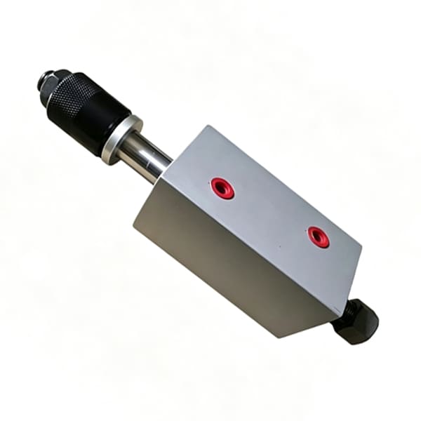
Mold Hydraulic Locking Cylinders
Your Reliable Supplier for Mold Hydraulic Locking Cylinders
We have many years of experience making mold compression hydraulic cylinders, and we've worked on projects for injection molding and die-casting plants. For example, some injection molding factories have broken old locking cylinders with no drawings available, we take apart the old parts and record everything. We measure important dimensions like mounting distance, cylinder bore, and rod diameter, then reverse-engineer them to create new drawings. We also check the injection molding machine model and clamping force provided by the customer to calculate and make sure the new cylinder's output meets the machine's clamping requirements. After replacement, the clamping equipment runs steadily. This also shortens lead time and cuts down production-line downtime.
We will review your drawings and actual working conditions before manufacturing. If needed, we can also offer optimized solutions based on rich experience, to deliver hydraulic cylinders with reliable quality.
Mold Hydraulic Locking Cylinders
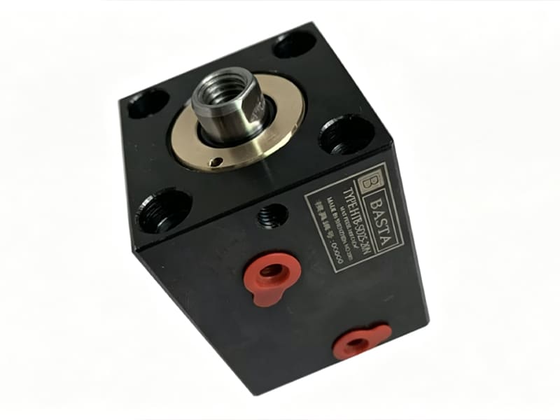
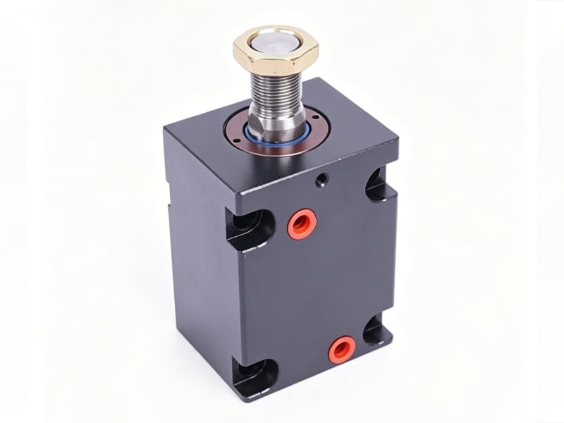
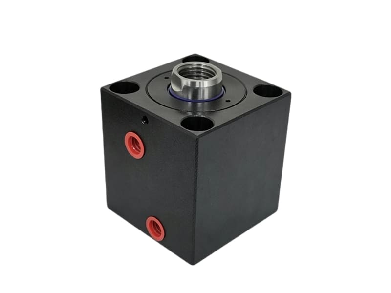
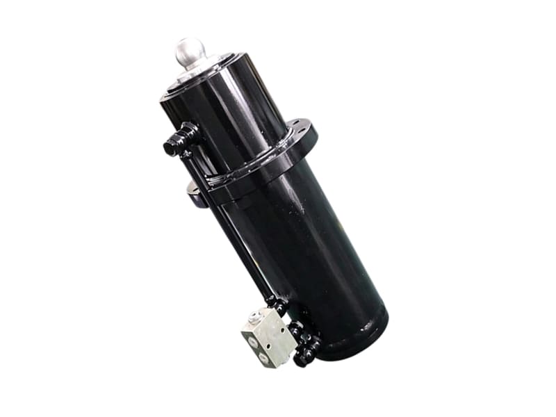
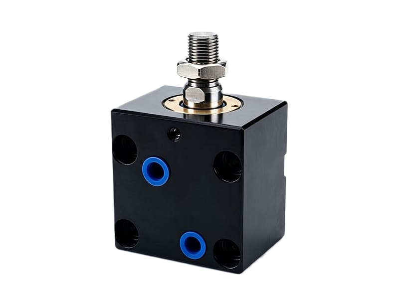
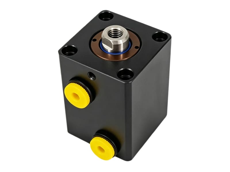
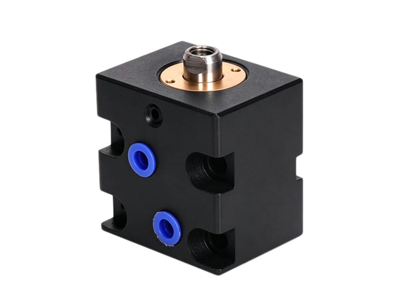
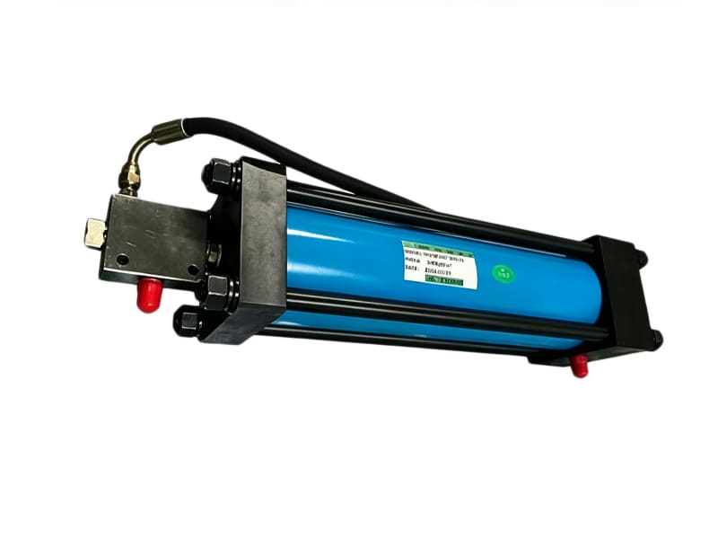
Applications of Mold Hydraulic Locking Cylinders
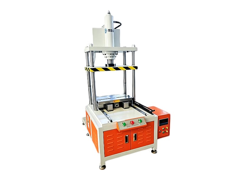
Press-fit Machine Positioning Stations
Mold-locking hydraulic cylinders are used in press-fitting positioning equipment, the piston rod extends to clamp the workpiece, when in position, an internal locking ring mechanically locks it in place. After pressing, oil is supplied to unlock it, and the piston rod retracts, releasing the workpiece and sending it to the next process. The cylinder features double-sided mechanical locks to keep the workpiece from shifting during press-fitting and reduce dimensional errors.
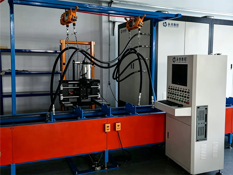
Automated Test Benches
Mold-locking hydraulic cylinders are also used in automated test equipment. The test piece is placed on the fixture of the middle plate. When it is in place, the hydraulic cylinder pushes out the piston rod to press and lock the middle plate, let the piston rod of the test piece is precisely aligned with the piston rod of the loading cylinder for the test. The mechanical lock of the mold-locking hydraulic cylinder is not affected by oil pressure or oil temperature, it haves high repeat locking accuracy, so even with mass testing, the test data stays accurate and reliable.
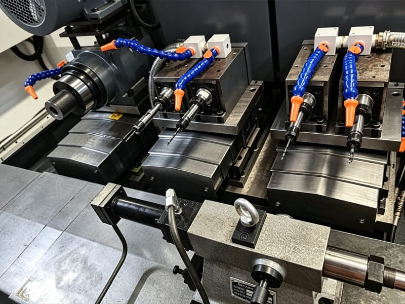
Machine Tool Hydraulic Slides
Mold-locking hydraulic cylinders are used in hydraulic tooling slides for machine tools. After the slide moves to the machining position, the piston rod extends to push the locking block and clamp the slide. When it reaches the set pressure, the piston rod locks, and you can start milling, drilling, or other operations. Unlike standard cylinders that rely on continuous hydraulic pressure, these cylinders hold the slide with a mechanical lock, this helps resist cutting vibration, keeps the slide table from moving, and improves machining accuracy.
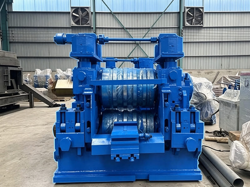
Metallurgical Roll-gap Adjusters
Mold-locking hydraulic cylinders are used for roll-gap adjustment in metallurgical equipment. Once the roll chock is in position, the cylinder extends to push the locking wedge into the gap, the internal mechanical lock rigidly secures the chock to keep the roll gap fixed so they can start rolling. After finishing, oil is supplied to unlock it.When the cylinder is locked, the hydraulic system can be depressurized, so the pump doesn't have to keep running. This cuts down energy consumption and heat buildup, and also helps extend the life of the pump and valve group.
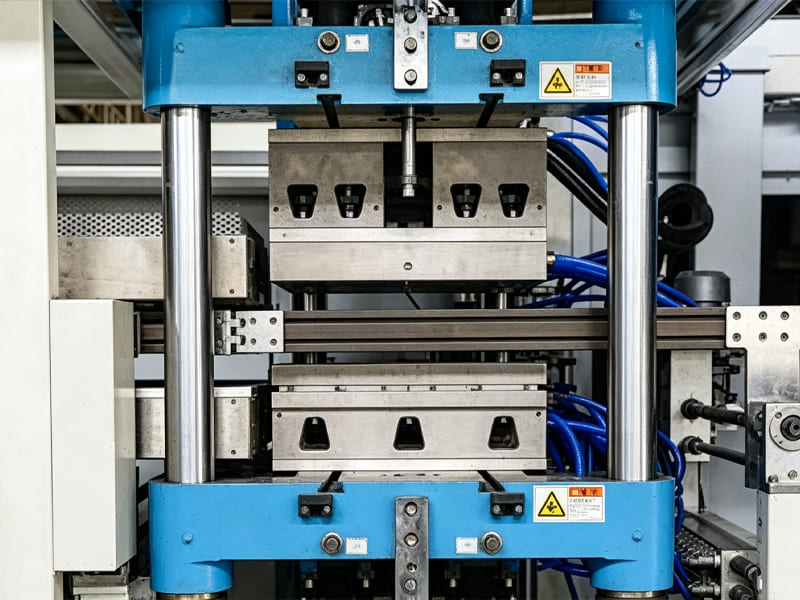
Packaging Machine Clamping Stations
Mold-locking hydraulic cylinders are used in packaging-machine clamping units. When the packaged material arrives at the working station, the cylinder pushes the clamping plate to hold the material, then it can seal, cut, or do other operations on the material. The cylinder locks and unlocks very quickly within milliseconds, matching the high-speed production rhythm of packaging machines.
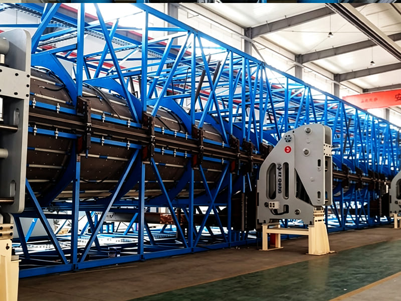
Wind-power Equipment Position Units
Cylinder Dimensions Too Large to Fit in Mold Cavity
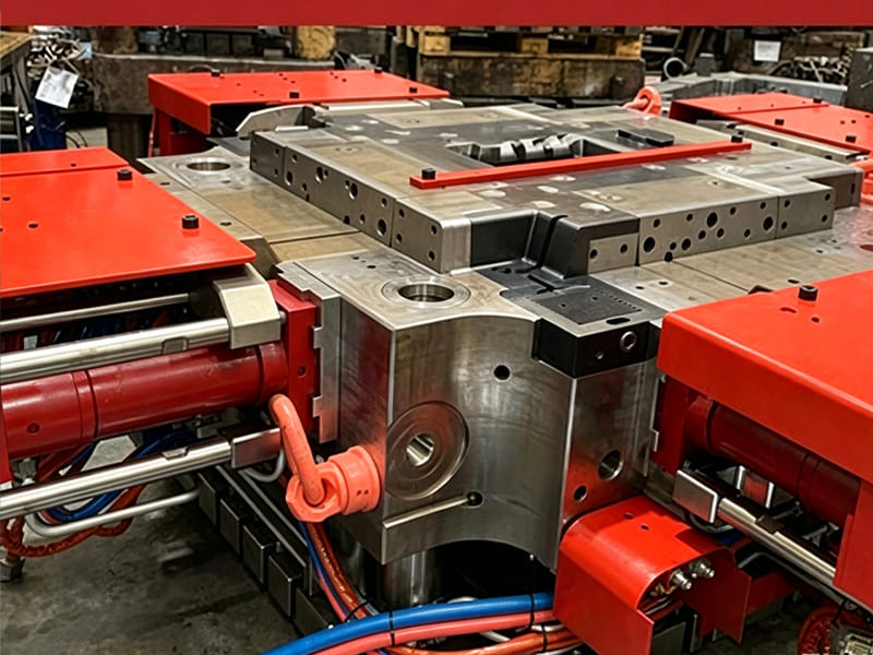
There's a lot of parts packed inside the mold, so there's not much room to install a cylinder.Standard-size hydraulic cylinders are bulky and tend to interfere with cooling pipes and mold parts. Some customers try to carve out a slot in the mold frame to make the cylinder fit, but that adds cost and weakens the structure, which can cause molding defects.
We reduce the cylinder footprint by optimizing key dimensions such as head and end cap thickness as well as port positions. While keeping strength and clamping force unchanged, we thin the flanges of the cylinder head and end cap and shorten piston-rod guide sections to cut overall cylinder length. We also move the oil ports to the rear or end face, so the fittings don't take up radial space. This way, the cylinder fits smoothly into tight mold spaces and avoids interference issues.
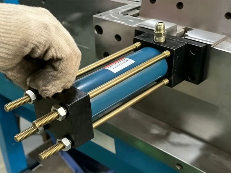
Wear or Jamming of The Locking Mechanism
The cylinder does repeated locking and unlocking over long periods, constant movement causes wear on the tapered surface of the locking ring, ruining the fit between the locking ring and piston rod. As a result, the locking ring may get stuck on the piston rod. Even with unlocking oil pressure supplied, the cylinder cannot release. The rod won't retract; the mold stays closed and the whole injection-molding machine has to stop.
Our locking rings are made of bearing steel or alloy tool steel and vacuum-heat-treated to reach HRC 58-62 hardness. This resists plastic deformation and adhesive wear under frequent friction. For the piston rod, we plate the locking groove with hard chrome, then precision-grind the surface so its hardness and roughness match the locking ring. This helps it resist deformation and uneven wear from constant friction.
No Cushioning – Impact Damages Mold at Stroke End
When the cylinder piston moves to the end of its stroke, if there's buffer structure, it hits the cylinder head or base with a hard metal-to-metal impact, that creates a big shock load. It also affects the mold; shock forces will transfer to the mold base and create vibration. Over time, this vibration wears down the parting surfaces, which reduces precision and causes flash on the molded parts.
Our solution is to add adjustable buffer structure at both ends of the cylinder, the buffer plunger narrows the oil return passage to build up oil resistance and slow down the piston, so impact between the piston and cylinder body is avoided. We also adjust the clearance during assembly based on the actual working conditions. For example, in high-speed operation, we reduce the clearance to increase the cushioning effect, making sure the piston reaches the end without impact.
Certifications
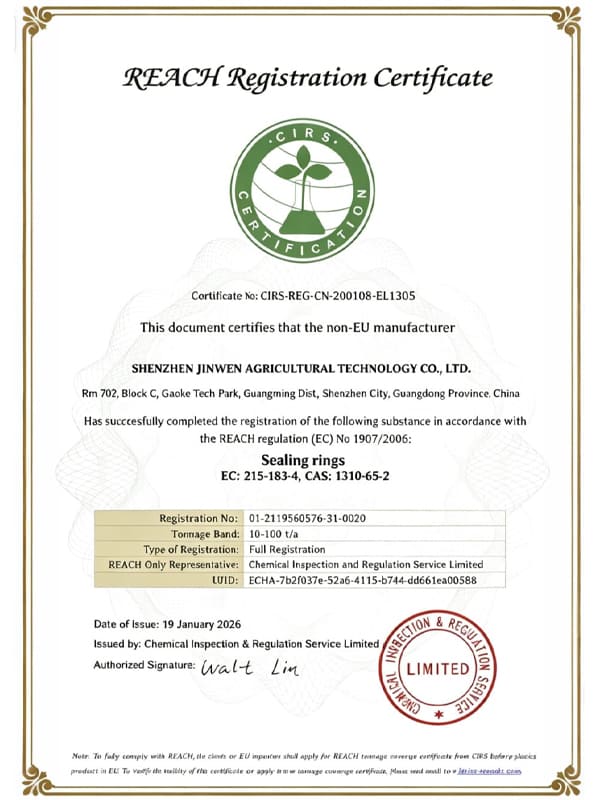
REACH Certificate
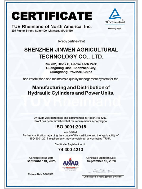
ISO 9001 Certificate
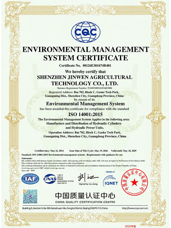
ISO 14001 Certificate
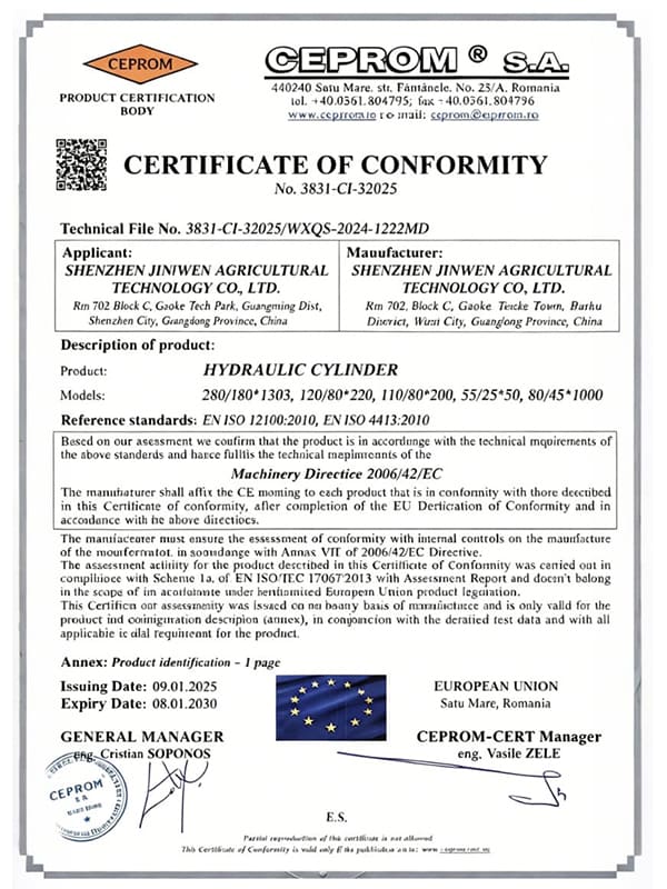
Certificate of Conformity
Why Work with Us
Mechanical Locking – Zero Leakage, Holds Even with Pressure Drop
We apply precision grinding on the locking ring bore to improve the fit between mating surfaces to ensure reliable locking.
Compact Slim Design – Fits Limited Mold Space
We move the oil ports to the side or rear to reduce mounting width and depth, so it fit into tight spaces.
High-Temperature Sealing – Resists 80-150°C Mold Heat
We use FKM seals on cylinders, this material withstands mold temperatures of 80–150°C, ensuring stable operation even at high heat.
Flexible Mounting – Custom Interfaces for Easy Integration
We can customize mounting interfaces and port locations base on your drawings, so the cylinder can be fitted directly after delivery without extra modification.
How to Customize Your Mold Hydraulic Locking Cylinder
Send Your Drawing
Provide us the detailed drawing or physical sample or critical dimensions, working pressure, mounting details.
Working Environment
Whether the cylinders works in high temperature, humidity, salt spray, dust and high frequency, pressure.
Get Quick Quote
We review all details of drawing and requirements and provide optimization suggestions with our experiences if necessary.
Production Procedure
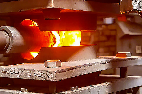
Integral forging
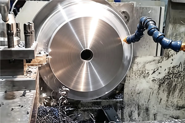
Turning
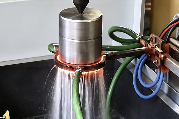
Induction hardening
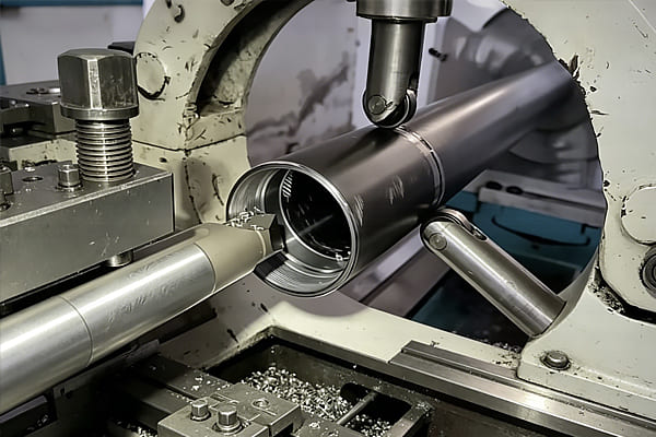
Cylinder barrel turning
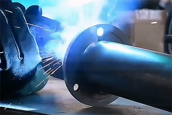
Welding
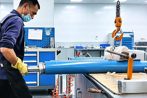
Assembly
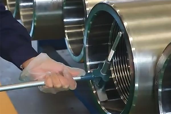
Dimensional measurement
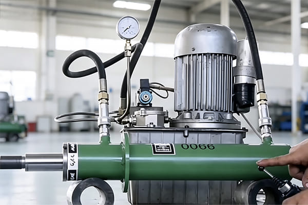
Pressure test