
Hydraulic Cylinder CNC Machining
After cutting the steels in the required sizes, they will be sent to the next step: CNC machining. This including the maching of cylinder barrel, piston rod, endcaps, bushings etc.
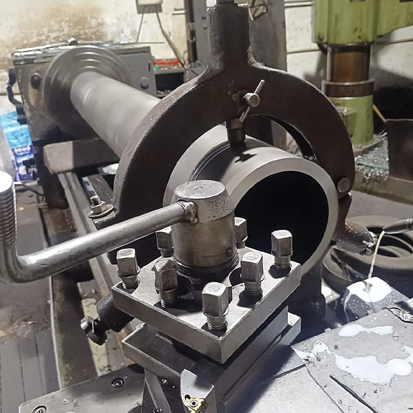
1. Cylinder Barrel Machining
For cylinder barrel machining, we first rough-turn the outer wall and machine a rough bore inside, leaving machining allowances on both inner and outer surfaces for later finishing. After rough machining, we do stress-relief annealing. We keep the temperature between 550℃ and 650℃, hold it for 2 to 4 hours, and then cool slowly to release internal stress. This prevents the part from deforming after final finishing.
The key processes for our cylinder barrels are fine boring and burnishing. Both are finishing steps for the bore. With fine boring, we keep roundness and cylindricity of the bore within 0.005 mm. Every cross-section of the barrel stays nearly round, and the bore size stays consistent all the way along. Then we use burnishing to get the bore surface roughness down to Ra0.2-0.4μm. During burnishing, the surface metal on the bore plastically deforms, making the metal structure denser. The surface hardness of the bore rises by 15% to 30%. This process also creates inward compressive stress on the bore. This compressive stress offsets the tensile stress created by hydraulic pressure when the cylinder operates. It improves the barrel’s fatigue resistance and helps avoid fatigue cracks.
Besides, for the barrel’s two ends, we machine features like shoulders, connecting threads and seal grooves, all in one setup. We won’t take the part off and re-clamp it mid-process. This keeps all these features concentric. After assembly, the seals bear the load evenly, lowering the risk of oil leakage.
2. Piston Rod Machining
For piston rod machining, we first grind the center holes from both ends of the rod. We machine the rod with these ground center holes as our positioning reference. We keep the piston rod’s concentricity error within 0.01 mm. That means the center line of every outer cylindrical surface along the whole rod lies on one straight line, with maximum deviation no more than 0.01 mm.
We turn a small groove, which we call a relief groove, at the thread runout on the piston rod, and round all sharp corners on this groove with a radius no less than 0.5 mm. This prevents stress concentration. We also turn an annular groove for the retaining ring, and hold its width tolerance within ±0.03 mm.
After grooving, we finish-grind the rod’s outer circle and keep the piston rod’s straightness error within 0.003 mm per meter.
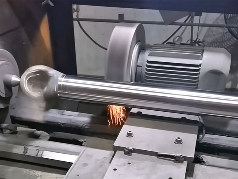
3. Other Parts Machining

We also machine the guide sleeve mounting bore, rod seal groove and wiper groove on them. For finish machining, we aim to machine the spigot, guide sleeve mounting bore and rod seal groove in one setup. This keeps the spigot concentric with the guide sleeve mounting bore, with concentricity error within 0.03 mm. It reduces oil leakage risk from uneven piston rod wear. For guide sleeves, we also use one setup to machine both the inner bore and outer circle together. We fine bore the inner bore first, then roll it, keeping the guide sleeve’s inner bore and outer circle concentric, and the concentricity error stays within 0.03 mm. We also keep the inner bore surface roughness within Ra 0.4 μm.
We also hold tight tolerances for piston machining. After pressing the copper bushing or guide ring onto the piston, we rework the copper bushing’s inner bore to remove deformation caused by pressing. We keep bore roundness within 0.02 mm, so the bore stays nearly perfectly round. That lets the piston rod slide smoothly and cuts down wear. Now for hinge lugs. After stress relief, we perform finish turning. Next we mill the mounting flat for equipment connection and the keyway to stop the lug from spinning. Finally, we bore the hinge pin hole for the pin to form a pivoting connection. We keep flatness error over the entire contact area of the lug’s mounting flat within 0.05 mm, so it fits tightly during assembly. The keyway’s position offset relative to the centerline is kept within 0.03 mm. This stops the key from shifting sideways and ensures even load sharing.
Leveraging our full in‑house manufacturing capacity, we are ready to develop custom hydraulic cylinder solutions for your project. Please get in touch with us today.
Contact Us